
Some of the important and relevant terms for sewer system are discussed below….
Sewage
It is Liquid Waste or Waste Water produce as a result of water use.Sewer
It is the pipe or conduit for carrying sewage. It is generally closed and flow takes place undr gravity (Atmospheric Pressure).Sewerage
Sewerage is the system of collection of waste water and conveying it to a point of final disposal with or without treatment.
Sources of waste water
Following are the principal sources of waste water- Domestic
- Industrial
- Storm water
Domestic
It is the waste water from houses, offices, other buildings, hotels and institutions.Industrial
It is the liquid waste from the industrial places from their different industrial processes like dying, paper matting, tanneries, chemical industries, etc.Storm Water
It includes surface runoff generated from rainfall and the street wash.Types of Sewer Systems
Following are the types of sewerage
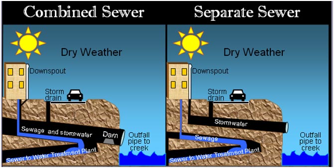
Separate System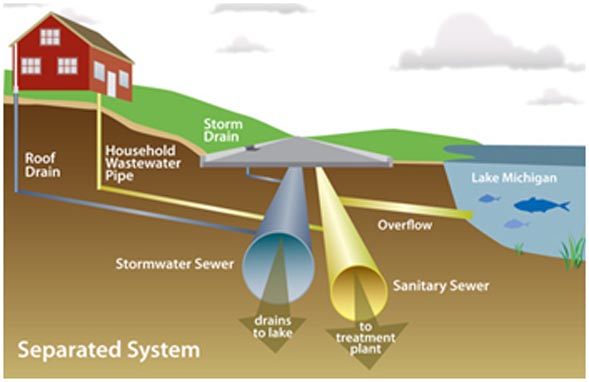
It is the system in which storm water is carried separately from
domestic and industrial waste water. This system is preferred when- There is an immediate need for collection of sanitary sewage but not for storm water
- When sanitary sewage needs treatment but the storm water does not

Combined System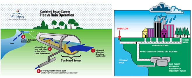
It is the type of system in which sewer carries both the sanitary and storm water. Combined system is favored when- Combined sewage can be disposed off without treatment
- Both sanitary and storm water need treatment
- Streets are narrow and two separate sewers can not be laid.
Types of Sewers

Sanitary Sewers
It carries sanitary sewage i.e. waste water from municipality including Domestic and Industrial wastewaters.
Storm Sewer
It carries storm sewage including Surface Runoff and Street Wash.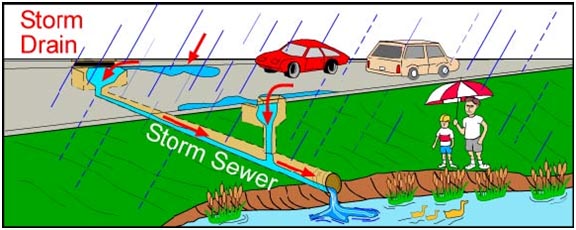
Combined Sewer
It carries domestic, industrial and storm sewage.House Sewer
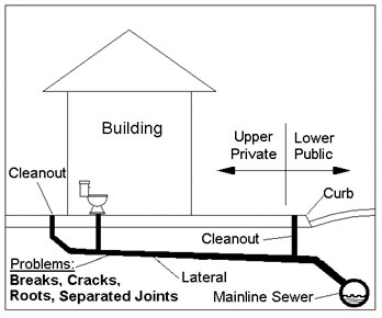
It is the sewer conveying sewage from plumbing system of building to common/municipal sewers.Lateral sewer
This sewer carries discharge from two or more house sewers.Sub-Main Sewer
This sewer carries discharge from two or more laterals.Main/ Trunk Sewer
It receives discharge from two or more sub-mains.Outfall Sewer
It receives discharge from all collecting system and conveys it to the point of final disposal.
Sewage flow
It is flow derived from the sanitary and industrial sewage that is the raw water from these industries and houses, so it means it has direct relation with the amount of water consumed.Generally 80 to 90 % of the water consumption is taken as sewage or waste water flow.
Variation in sewage flow
Like water supply, sewage flow varies from time to time. Since sewers must be able to accommodate Maximum Rate of Flow, the variation in the sewage flow must be studied.Generally Herman Formula is used to estimate the ratio of Maximum to Average Flow

WASA Lahore Design Considers the following relationship for sewer design
| Average Sewage Flow (m3 /day) | Peak Factor |
| ≤ 2500 | 4.0 |
| 2500 – 5000 | 3.4 |
| 5000 – 10000 | 3.1 |
| 10000 – 25000 | 2.7 |
| 25000 – 50000 | 2.5 |
| 50000 – 100000 | 2.3 |
| 100000 – 250000 | 2.15 |
| 250000 – 500000 | 2.08 |
| > 500000 | 2.0 |
Infiltration
It is amount of water that enters into the sewers through poor joints, cracked pipes, walls and covers of manholes.- It is nonexistent during dry weather but increases during rainy season.
- Water and Sanitation Agency (WASA) Lahore uses the following infiltration rates for the design of sewer system.
| Sewer Diameter | Infiltration |
| 225 mm to 600 mm | 5 % of Avg. Sewage Flow |
| > 600 mm | 10 % of Avg. Sewage Flow |
Design Period
Sewer System
Period of design is indefinite. The system is designed to take care for the maximum development of the area. But we take design period of 20 years for our sewer system.Sewer Pumping Station
- Design period is 10-years.
- Rate of Flow are average daily, peak and minimum flow including Infiltration.
PROJECT DESCRIPTION
The project is based on the design of Partially combined sewerage system of a community which is having approximately a flat terrain because the difference in the reduce levels is very small. I have designed the sewage pumping station along with the hydraulic statement and the required drawings plus some extra drawings. I am confident that my design will work successfully and there will be not any problems. The Layout of the community is given as under.
DESIGN CRITERIA
Design Flow
First of all calculate the average sewage flow on the basis of water consumption and the population at the end of the design period. i.e at the full development of the area. Then the design flow for sanitary sewer and partially combined sewers can by calculated by using the following formulae.- For Sanitary Sewer
Qdesign= Peak sewage flow + infiltration
- For partially combined sewer (WASA Criteria)
Design Equation
Manning’s Equation is used for sewers flowing under gravity
V = Velocity of flow in m/sec
R = Hydraulic mean depth (A/P) = D/4 when pipe is flowing full or half full
S = Slope of the sewer
n = Coefficient of roughness for pipes
Minimum (Self Cleansing) Velocity
Sewage should flow at all times with sufficient velocity to prevent the settlement of solid matter in the sewer. Self Cleansing Velocity is the minimum velocity that ensures non settlement of suspended matter in the sewer.The following minimum velocities are generally employed
- Sanitary sewer = 0.6 m/sec
- Storm sewer = 1.0 m/sec
- Partially combined sewer = 0.7 m/sec
Maximum velocity
The maximum velocities in the sewer pipes should not exceed more than 2.4 m/sec. This max velocity in the sewer should not exceed this limit of 2.4 m/sec. It is to avoid the excessive sewer abrasion and also to avoid steep slopes.Minimum Sewer Size
225mm is taken as the minimum sewer size. The reason being that, the choking does not take place even with the bigger size particles, which are usually thrown into the sewer through manholes.Minimum Cover of Sewer
1m is taken as the minimum cover over the sewers to avoid damage from live loads coming on the sewer.Spacing of Manhole (WASA, Criteria)
For (Sewer Size) 225mm to 380mm spacing not more than 100mFor (Sewer Size) 460mm to 760mm spacing not more than 120m
For (Sewer Size) greater than 760mm spacing not more than 150m
Direction of Sewer Line
Sewer should flow, as for as possible the Natural Slope.Design of Sewer
- Size of Sewer
Qf = A x V
- Slope of Sewer
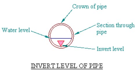
Invert Level
The lowest inside level at any cross-section of a sewer pipe is known as Invert Level at that Cross-section.
Invert Level = NGSL/Road Level – Depth of Sewer – Thickness of Sewer – Dia. of Sewer
Joints in Sewers
- Bell & Spigot Joint
- Tongue &Groove Joint
Manholes
These are provided for
- Cleaning
- inspection and
- house connection
- Change in Sewer direction
- Change in sewer diameter
- Change in slope
SEWERAGE DESIGN DATA
No of Plots = 281
No of Apartments = 3
No of Flats = 3
Design period = 20 years
POPULATION FORECAST
| Present (2009) | Design (2029) | |
| Persons/plot | 7 | 10 |
| Persons/apartment | 400 | 600 |
| Persons/flat | 200 | 400 |
POPULATION FORECASTING
Present Population Pp= 1) 281×7+400×3+200×3 = 3767
Design Population Pd= 2) 281×10+600×3+400×3 = 5810
Annual Growth Rate = 2.1% (For Pakistan, 2008 report)
Design Population Pd= 2) 281×10+600×3+400×3 = 5810
Annual Growth Rate = 2.1% (For Pakistan, 2008 report)
Design Population Pd
1) Pd = Pp x (1+2.1/100)20
Pd = 3767x(1+2.1/100)20 = 5709
Pd = 5810 ( From Table)
Per capita water consumption = 350 + 44= 394 lpcd (liters per capita per day)
Average Design flow = Pd x water consumption x 0.8 / 1000
(80% goes to sewers as waste water)
= (394 x 5810 x 0.8 ) / 1000
Qavg = 1831.312 m3/day
Peak factor = 4 (from WASA table)
To Check Infiltration rates


DESIGN OF WET WELL
Qmax = 14742.1m3/day = 10.237 m3/minPumping capacity
P = Qmax = 10.237 m3/min
Minimum cycle time
Minimum Cycle time must not be less than 5-minutes
For smaller pumps t min = 15 min
Volume = V = [P x t(min)]/4
Effective Volume = ( 10.237 x 15 ) / 4 = 38.39 m3
DIMENSIONS OF WET WELL
Length = 3.6 mWidth = 3.6m
Height = 3 m
Volume = 3.6*3.6*3 = 38.88m3
Pump must run for at least 2 minutes
Check the cycle time , should be greater than 2 minutes
t = V/(P-Qmin) = 38.39 / (10.237 – 0.6358) = 3.99~=4
So 4 minutes is greater than 2 minutes ..( OK)
Cycle Time for Minimum and Average Flow
CYCLE TIME = t = (V/(P-Q))+(V/Q)For Qmin = 38.39 / (10.237 – 0.6358) + 38.398/0.6358 = 64.391 min > 15min (OK)
For Qavg = 38.39 / (10.237 -1.271) + 38.39/1.271 = 34.48 min > 15min (OK)


MANHOLE

DROP MANHOLE

SEWER JOINTS

SEWER BEDDINGS

COMMENTS
- This design is based on partially combined sewerage system thus is economic.
- All the necessary things are taken from the WASA tables and Minimum velocity is taken as 0.6 m/sec which is the self cleansing velocity and velocity must not be more than 2.4 m/sec.
- Minimum diameter of sewer is taken as 225 mm and other diameters are rounded to the locally available in the market according to WASA standards.
- Minimum rate of sewage flow is taken as 50% of average sewage flow.
- Minimum clear cover of 1-m is provided above the sewer in order to avoid from impact of live loading.
- Flush tanks are provided where velocity is less than 0.6 m/Sec.
RESULTS
- Diameters are less then 600mm so Infiltration rate used is 5% of average sewage flow.
- Bell & Spigot joints have been used as the diameters are less then 600mm.
- One Drop Manhole is coming at M15 as the vertical drop is more than 0.6m.
- In Sewers (M9-M8, M8-M11, M10-M11, M12-M13, M5-M18, M20-M21, M24-M21, M21-M22, M25-M26), Velocity is less than the self cleansing velocity So, Flush tanks will be provided here.
- Most of the diameters are of 225mm ensuring the economic side of the project.
- Wet well dimensions are 2.5×3.5×4.4.
- Cycle time of 15 minutes is satisfied ensuring the adaptability of small pumps so more economic.
RECOMMENDATIONS
- Flush tanks should be flushed once in 24 hours to avoid sediment deposition.
- If the sewer is to be laid under the water table then crushed stone bedding should be used.
- Sewers should be joined in a manhole keeping the crowns at the same level.
No comments:
Post a Comment